Thermocouple compensating wires refer to a pair of wires with insulated layers that have the same nominal value as the thermoelectromotive force of the matched thermocouple within a certain temperature range (including normal temperature), and use them to connect the thermocouple and the measuring device. To compensate for the error caused by the temperature change at the junction between them and the thermocouple. Compensation wires are divided into extension compensating wire and compensation type compensating wire.
There are many types of compensation wires for thermocouple. Under different operating temperatures and some special environmental conditions, it is particularly important to choose compensation wires that match the thermocouple. Understanding the related concepts of compensating wires for thermocouple: main model, structure, technical requirements, selection, use, and dealing with some influencing factors in use, which play a very important role in the accurate measurement of temperature by thermocouple.
1. Concept
(1) Extension compensating wire. It refers to the nominal chemical composition of the alloy and the nominal value of the thermal electromotive force are the same as the matching thermocouple wire, which is represented by the letter "X" appended to the thermocouple graduation number, such as "KX";
(2) Compensation type compensating wire. It means that the nominal chemical composition of the alloy is different from that of the matching thermocouple wire, but its thermoelectromotive force value is the same as that of the matching thermocouple at 0-100°C or 0-200°C. The value is the same, it is represented by the letter "C" appended to the thermocouple graduation number, such as "KC". Different alloy wires can be applied to thermocouple with the same graduation number, and are distinguished by additional letters, such as "KCA" and "KCB";
(3) Tolerance (or permissible error). The tolerance for compensating wires for thermocouple is the maximum deviation due to the use of compensating wires in the measurement system. The value is expressed in microvolts (μV), and its tolerance is divided into precision grade and common grade. The tolerances of compensation wires for various thermocouple should meet the requirements in Table 1;
(4) Reciprocating resistance. It refers to measuring the resistance value of the positive pole and the negative pole of the 1m-long compensation wire at 20°C, and the sum of the resistance values of the positive and negative poles is called the reciprocating resistance of the compensation wire. The reciprocating resistance of the compensation wires for various thermocouple at 20°C should meet the requirements in Table 2.
|
Graduation
number
|
Type
|
Thermoelectric potential & tolerance value
|
Measuring end
temperature/℃
|
|
|
|
100℃
|
200℃
|
|
|
|
|
thermoelectric
potential
|
Tolerance
|
thermoelectric
potential
|
Tolerance
|
|
|
|
|
|
Ordinary
|
Precision
|
|
Ordinary
|
Precision
|
|
|
S/R
|
SC/RC
|
645
|
±60(±5℃)
|
±30(±2.5℃)
|
1440
|
±60(±5℃)
|
|
1000
|
|
K
|
KCA
|
4095
|
±100(±2.5℃)
|
±60(±1.5℃)
|
8137
|
±100(±2.5℃)
|
±60(±1.5℃)
|
1000
|
|
|
KCB
|
4095
|
±100(±2.5℃)
|
±60(±1.5℃)
|
|
±100(±2.5℃)
|
±60(±1.5℃)
|
900
|
|
|
KX
|
4095
|
±100(±2.5℃)
|
±60(±1.5℃)
|
8137
|
±100(±2.5℃)
|
±60(±1.5℃)
|
900
|
|
N
|
NC
|
2774
|
±100(±2.5℃)
|
±60(±1.5℃)
|
5912
|
±100(±2.5℃)
|
±60(±1.5℃)
|
900
|
|
|
NX
|
2774
|
±100(±2.5℃)
|
±60(±1.5℃)
|
5912
|
±100(±2.5℃)
|
±60(±1.5℃)
|
900
|
|
E
|
EX
|
6317
|
±200(±2.5℃)
|
±120(±1.5℃)
|
13419
|
±200(±2.5℃)
|
±100(±1.5℃)
|
500
|
|
J
|
JX
|
5268
|
±140(±2.5℃)
|
±85(±1.5℃)
|
10777
|
±140(±2.5℃)
|
±85(±1.5℃)
|
500
|
|
T
|
TX
|
4277
|
±60(±1.0℃)
|
±30(±0.5℃)
|
9286
|
±90(±1.5℃)
|
±48(±0.5℃)
|
300
|
|
WC3
|
WC3/25
|
1145
|
±48(±1.0℃)
|
|
2602
|
±80(±1.5℃)
|
|
|
|
WC5
|
WC5/26
|
1451
|
±51(±1.0℃)
|
|
3089
|
±85(±1.5℃)
|
|
|
Table 1
|
Type
|
(Ω/m)
|
|
|
0.2mm2
|
0.5mm2
|
1.0mm2
|
1.5mm2
|
2.5mm2
|
|
NC/BC
|
0.25
|
0.1
|
0.05
|
0.03
|
0.02
|
|
KCA
|
3.5
|
1.4
|
0.7
|
0.47
|
0.28
|
|
KCB
|
2.6
|
1.4
|
0.7
|
0.47
|
0.28
|
|
KX
|
5.5
|
2.2
|
1.1
|
0.73
|
0.44
|
|
EX
|
6.25
|
2.5
|
1.1
|
0.73
|
0.44
|
|
JX
|
6.25
|
2.5
|
1.25
|
0.83
|
0.5
|
|
TX
|
3.25
|
1.3
|
0.65
|
0.43
|
0.26
|
|
NC/BC
|
3.75
|
1.5
|
0.75
|
0.5
|
0.3
|
|
NC/BC
|
7.15
|
2.86
|
1.43
|
0.95
|
0.57
|
|
WC3/25
|
0.5
|
0.2
|
0.1
|
0.07
|
0.04
|
|
WC5/26
|
0.5
|
0.2
|
0.1
|
0.07
|
0.04
|
Table 2
|
Type
|
Graduation
number
|
Compensation wire alloy wire
|
Insulation coloring
|
|
|
|
positive
|
negetive
|
positive
|
negetive
|
|
BC
|
B
|
CU
|
CU
|
RED
|
GREY
|
|
SC
|
S
|
CU(SPC)
|
CUNI(SNC)(0.6)
|
RED
|
GREEN
|
|
RC
|
R
|
CU(RNC)
|
CUNI(RNC)(0.65)
|
RED
|
GRREN
|
|
KCA
|
K
|
FE(KPGA)
|
CUNI(KNCA)(22)
|
RED
|
BLUE
|
|
KCB
|
|
CU(KPGB)
|
Constantan(KNCB)(40)
|
RED
|
BLUE
|
|
KX
|
|
NICR(KPX)(10)
|
NISI(KNX)(3)
|
RED
|
BLACK
|
|
NC
|
N
|
FE(NPC)
|
CUNI(NNC)(18)
|
RED
|
GREY
|
|
NX
|
|
NICRSI(NPX)(14)
|
NISI(NNX)(4)
|
RED
|
GREY
|
|
EX
|
E
|
NICR(EPX)(10)
|
CUNI(ENX)(45)
|
RED
|
BROWN
|
|
JX
|
J
|
FE(JPX)
|
CUNI(JNX)(45)
|
RED
|
PURPLE
|
|
TX
|
T
|
CU(TPX)
|
CUNI(TNX)(45)
|
RED
|
WHITE
|
|
WC3/25
|
WC3
|
WPC3/25
|
WNC3/25
|
RED
|
YELLOW
|
|
WC5/26
|
WC5
|
WPC5/26
|
WNC5/26
|
RED
|
ORANGE
|
Table 3
2. Main Type
See Table 3 for the main types of compensating wires used for thermocouple, the regulations and requirements for matching thermocouple, materials and the color of the insulation layer.
3. Structural and Technical Requirements
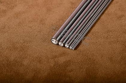
The structure of the compensation wire generally consists of a conductor, insulation, sheath or shielding. Its structure and main technical requirements are as follows:
(1) Conductor. The conductor material should be selected according to the type of compensation wire. See Table 3 for specific materials. The wire core is divided into two types: single wire and multi-stranded wire, and the specific specification (wire cross section) ranges from 0.2mm2 to 2.5mm2; the reciprocating resistance value at 20°C should meet the requirements in Table 2;
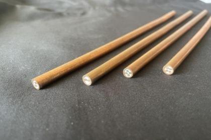
(2) Insulation. The insulating material of ordinary compensation wire is polyvinyl chloride insulating material. The surface of the insulating layer should be flat, uniform in color and free from mechanical damage; 90% of the nominal value -0.1mm; the insulation layer should withstand the spark test of AC 50Hz and voltage of 4000V without breakdown, and the running speed of the spark tester should ensure that the time for each point of the insulation layer to withstand the voltage is not less than 0.1s.
The insulation of the heat-resistant compensating wire is PTFE. The tolerance of insulation thickness shall not exceed -20% of the nominal value, and the thickness of the thinnest part shall not be less than 90% of the nominal value;
(3) Jacket. The sheath material of ordinary compensating wire is PVC sheathing material. The sheath should be tightly wrapped on the insulating layer of the wire core, the insulating layer and the sheath should not adhere, the surface should be flat, and the color should be uniform; the allowable deviation of the sheath thickness is -20% of the nominal thickness, and the thickness of the thinnest part should be Not less than 80% of the nominal value.
The sheath material of the heat-resistant compensation wire is made of PTFE sheath material or alkali-free glass wool. ThePTFE sheath should be tightly wrapped on the insulating layer of the wire core, the insulating layer and the sheath should not stick together, the surface should be flat, and the color should be uniform; the allowable deviation of the sheath thickness is -20% of the nominal thickness, and the thinnest part The thickness should not be less than 80% of the nominal value. For the sheath woven with alkali-free glass filaments, the weaving density should not be less than 90%;
(4) Shield. The shielding layer is mainly braided with tinned copper wire or galvanized steel wire, wrapped with aluminum-plastic composite tape and copper-plastic composite tape. Use braided shielding with a braiding density of ≥80%, and the broken ends should be trimmed neatly after splicing. When wrapping shielding is used, the aluminum (copper) composite tape should be closely attached to the insulating layer, and it is not easy to loosen; the thickness of the shielding layer should not be greater than 0.8mm.
4. Selection
4.1. Advantage
Each type of thermocouple has its matching compensation wire. When selecting the compensation wire, it must be selected correctly according to the type of thermocouple and the occasion used. Otherwise, not only will the compensation effect not be achieved, but the error may be increased. For example, K-type thermocouple should choose the compensation wire of K-type thermocouple, and select the working temperature range according to the application. Usually, the working temperature of KX narrow range is -20~100°C, wide range is -25~200°C, the temperature tolerance of ordinary grade is ±2.5°C, and the tolerance of precision grade is ±1.5°C. The thermoelectric potential generated by the B-type thermocouple at room temperature is very small, and the compensation wire is generally not needed for high temperature measurement. Just use ordinary copper core insulated wire.
When the temperature at the junction between the compensation wire and the thermocouple is lower than 100°C, a common compensation wire with a general sheath can be used. When the temperature is between 100 and 200°C, a heat-resistant compensating wire with a heat-resistant sheath should be selected, and the extension type is suitable. In an environment with electromagnetic field interference, in order to improve the anti-interference performance of the compensation wire for thermocouple, tinned copper wire or galvanized steel wire braiding, copper-plastic tape or aluminum-plastic tape should be used to wrap the shielding compensation wire. However, the shielding layer must be strictly grounded, otherwise the shielding layer will not play the role of shielding, but will enhance the interference.
5. Use
(1) The two junctions of the thermocouple terminal should be as close as possible, and the temperature of the two junctions should be kept as consistent as possible; the connection with the two junctions of the instrument terminal should also be as consistent as possible.Where the fan is installed, avoid blowing the fan directly to the connection point;
(2) Because the signal generated by the thermocouple is very weak, on the order of microvolts. If the distance used is too long, due to signal transmission attenuation and strong electric interference coupling in the environment, it is enough to distort the signal of the thermocouple, resulting in inaccurate measurement and control of temperature, and temperature fluctuations in severe cases. Usually the length of the thermocouple compensation wire should be controlled below 15m. If it exceeds 15m, it is recommended to use a temperature transmitter for signal transmission. The temperature transmitter converts the potential value corresponding to the temperature into a DC current transmission, and has strong anti-interference.
(3) The wiring of the compensation wire must be far away from the power line and the source of interference. When it is unavoidable to pass through, the way of crossing and swapping should be adopted as much as possible, and parallel laying should not be used.
(4) The positive and negative poles of the compensation wire must correspond to the positive and negative poles of the thermocouple, otherwise not only will the compensation effect not be achieved, but the error will be larger than that without the compensation wire. Therefore, the polarity must be paid attention to when the compensation wire is connected.
(5) When the compensation wire is used in precision measurement, the correction value of the compensation wire must be added to the measurement result.


 IPv6 network supported