1.Use other types of wires instead of compensation thermocouple wires
According to the
operation principle of thermocouple temperature measurement, the thermoelectric
potential of the thermocouple circuit is related to the measured temperature
and the temperature of the thermocouple reference end. In the industrial site,
the temperature of the thermocouple reference end is unstable and will be
influenced by its surrounding environment. With temperature fluctuation ofthe
reference end, the compensating wire is used to extend the
reference end to an environment with stable temperature or simply somewhere
away from the heat source to compensate the deviation caused by temperature
changeat the reference end.Other types of wires can
transmit the mV signal value generated by thermocouple temperature measurement,
but can not compensate the temperature of the thermocouple reference end, which
might result in inaccurate temperature compensation of thermocouple temperature
measurement system.
Correct method:For thermocouple signal transmission, we must use the
matching type of thermocouple compensating wires with the thermocouple , it is
prohibited to replace the compensating wire with a normal electric wire.
2.The insulation layer of the thermocouple compensating wire is damaged.
While connecting
the thermocouple, there might be certain degree of wear on the insulation layer
at the outlet of the thermocouple junction box or at other parts of the
compensating wire. As a result, the temperature display value on the display
instrument or in the DCS system is generally smaller than usual.
Correct method:Make sure to fix the insulation layer after finding
damaged parts on the thermocouple compensating wire, and restore the normal
display value of the control instrument or the paperless temperature recorder.
3.The measurement error occurs when the positive and negative polarity of the
thermocouple compensating wire is connected reversely.
The thermocouple
as well as the thermocouple compensating wire both have positive and negative
polarity.When the compensating wire is inversely connected, the display
value on the paperless temperature recording instrument changes greatly as
follows:
A. After
inversely connecting the polarity of the compensating wire, when the
temperature at the junction of the thermocouple and the compensating wire is
higher than the temperature in the control room, the temperatureshowedon the instrument will be lower than the actual measured temperature.
B. After
inversely connecting the polarity of the compensating wires, when the
temperature at the junction of the thermocouple and the compensating wire is lower
than the temperature in the control room, the temperatureshowedon the instrument will be higher than the actual measured temperature.
C. After
inversely connecting the polarity of the compensating wires, when the
temperature at the junction of the thermocouple and the compensating wire is
the same as the temperature in the control room, the temperatureshowedon the instrument will be the same as the actual measured temperature.
It is proved by
theory that the error caused by the reverse connection of the polarity of the thermocouple
compensating wire is about twice more than that when no compensating wire is
used.
Different types
of thermocouple compensating wires all have red insulation layer for the
positive polarity, but different colors for the negative polarity. As a result,
the type of compensating wires can be distinguished according to the color of the
insulation layer.
Correct method:Correctly distinguish the positive and the negative
polarity of the thermocouple as well as the thermocouple compensating wire, the
polarity can not be connected reversely.
4. Poor contact between the thermocouple compensating wire and the wiring
terminal
The thermocouple
compensating wire is relatively hard, so it is easy to have poor contact
between the wire and the wiring terminal when connecting or using it. There
might be no display value on the DCS system, or the display value might exceed
the range of the instrument measurement.
Correct method:Tighten up the wiring terminal and eliminate the poor
contact to restore the normal measurement display of the instrument.
5.The joint in the thermocouple compensating wire has poor contact
When producing
the thermocouple compensating wire, the number of joints per unit length is
limited by standards for the manufacturer. When the extension is needed in the
process of laying the compensating wire for long distance, the technician
commonly connects the joints of compensating wires together and then apply the
insulation on it directly. After using it for a period of time,inaccurate
measurement as well as increases the occurrence of deviation.
Correct method:if it is necessary to extend the length of the
compensating wire, connect the same polarity of the same type of compensating
wires together, weld firmly the connection point, and finally put it into use
after applying the insulation.
6.The signal will be interfered when the compensating wire is laid in
parallel with the power cable
An enterprise
laid thermocouple compensating wires and electrical power cables in the same
cable bridge during the construction. When the system was put into use, the DCS
system showed the thermocouple temperature rose and dropped unstably. After
careful inspection, it is confirmed that the thermocouple measurement signal is
interfered by the power line which caused the temperature measurement deviation
of 100℃.
Correct method:During the construction, lay the thermocouple
compensating wire and the power cable in the same direction, but lay the power
bridge and the signal instrument bridge separately with shielded compensating
wires. If the compensating wire has to be on the same bridge with the power
cable, shielding baffles or cross-laying method should be used inside the
bridge frame to minimize the interference of thermocouple signals.
7. Using the thermocouple compensating wire for long distance, measurement
errors might occur due to the signal attenuation and the interference
The electric
potential value generated during thermocouple temperature measurement is mV
signal. Due to the increase of the length of the compensating wire, the signal
attenuation and the on-site magneto-electric interference mix together, which
makes the temperature display value of the instrument or the DCS system
fluctuate.
Solution:
A. When laying
compensating wires for long distance is needed, the compensating wire’s
diameter should not be less than Φ1.5mm2 which can reduce the attenuation of
the mV signal.
B. Pick up the
shielded compensating wire and ground the shielding layer according to the
standard (the shielding layer must be grounded at the end of the compensating
wire, and the grounded layer should be incorporated into the grounding network
of the instrument signal, and the grounded layer should not be incorporated
into the electrical grounding network of the factory). This can avoid
measurement errors caused by incorrect method of grounding for the shielding
layer.
C. Use a
temperature transmitter to convert local thermocouple signal into the 4-20ma
signal in order to improve the anti-interference ability of the signal.
8. After using a temperature transmitter along with the thermocouple, the
compensating wire is not needed.
The thermocouple
temperature transmitter is usually installed in the thermocouple junction box
and the control cabinet, which are two different types of the temperature
transmitter:
A. The
temperature transmitter installed in the thermocouple junction box forms an
integrated thermocouple temperature transmitter. The thermocouple wires are
directly connected to the input end of the temperature transmitter, and the
output uses 2-wire system of 4-20mA signal. The transmitter is directly
connected to the display instrument or the DCS system with twisted pair cables
or two core shielded cable, without thermocouple compensating wires.
B. If the
temperature transmitter is installed in the control cabinet, the thermocouple
and the temperature transmitter must be connected with compensation wire. The
transmitter and the display instrument or DCS system shall be directly
connected with the twisted pair or the
two-core shielded cable, and the thermocouple compensating wire is not used in
this case.
Correct method: Based on the application scenario, we determine whether
the compensating wire needs to be used for the thermocouple temperature
transmission. A compensating wire must be used to connect the thermocouple and
the guide rail type of the temperature transmitter.
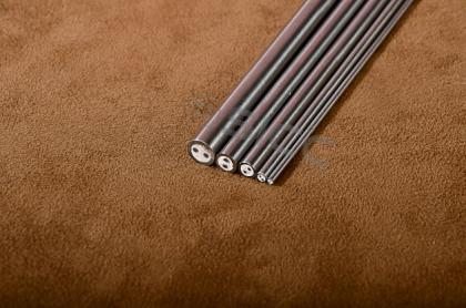
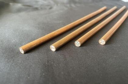
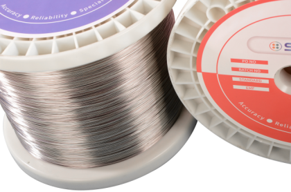
SICC provides various bare thermocouple wire,Type K,J,T,E,N thermocouple wire,extension thermocouple wire,get details from us quickly.


 IPv6 network supported